Intro or: The Wide World of Consumer Massage Guns
The market for handheld percussive therapy devices is an interesting one.
Companies like Therabody and Hyperice, who dominate the market, ship great devices, complete with sturdy and ergonomic designs, variable speed settings, and temperature control. However, these features come at a massive premium. (Ex: The popular Theragun Mini retails for $220, and the Hypervolt 2 for $229.)
My vision for a new project was to design and build a functional prototype that matched the performance of leading devices like the Theragun Mini but at a fraction of the cost, while also adding features like USB-C charging, heated massage, and variable speed control.
Academia and Personal Projects Collide
Around the same time I had the idea to build a new and improved percussive therapy device, our final project for the OU Electronics Lab course was assigned. Essentially, the point of the project was to apply any/all of the electronic design lessons we’d learned in the class throughout the semester to make “something cool.” (I’m paraphrasing, but that was the intent.)
I thought my idea for a Theragun alternative was pretty cool, so I decided that would be my final project. However, the only catch was that our designs could only include components that we used in the course. Since we only used simple components (resistors, diodes, caps, BJTs/MOSFETs) and some basic ICs (555 timers, ANDs, ORs), this ruled out using a microcontroller for the logic or a fancy USB-C port for power/data.
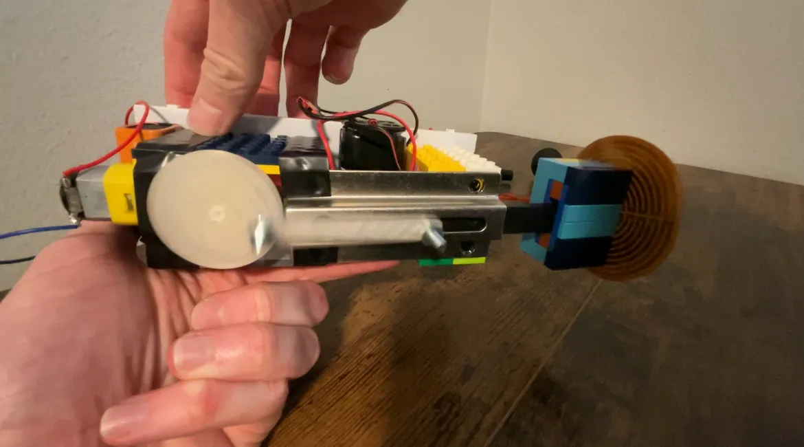
However, I adapted my plans to craft a DIY Theragun with variable speed control and heating (and it was a heck of a lot more affordable, too).
Check the video below for a short demo, or the video at the bottom of the page for an extended demo/explanation of my prototype.
Moving Forward
While the prototype I built for class was far from a commercial product, it demonstrated that I could readily build a much more sophisticated and capable device with more modern hardware.
If I didn’t have the time and budgetary constraints given for the school project, I would have soldered the circuitry to a test PCB board and designed an entire housing for the device in CAD (even though I think the LEGOs gave the device some charm).
To build on what I already have, I’m going to program several microcontroller development boards (Raspberry Pi Pico 2 W and a cheap ESP32) to control the logic. I’ll also design and test various CAD housings for the board, motor, and battery.
This has been a fun project so far, and I’m looking forward to sharing more progress!